1. How does a transformer transform voltage?
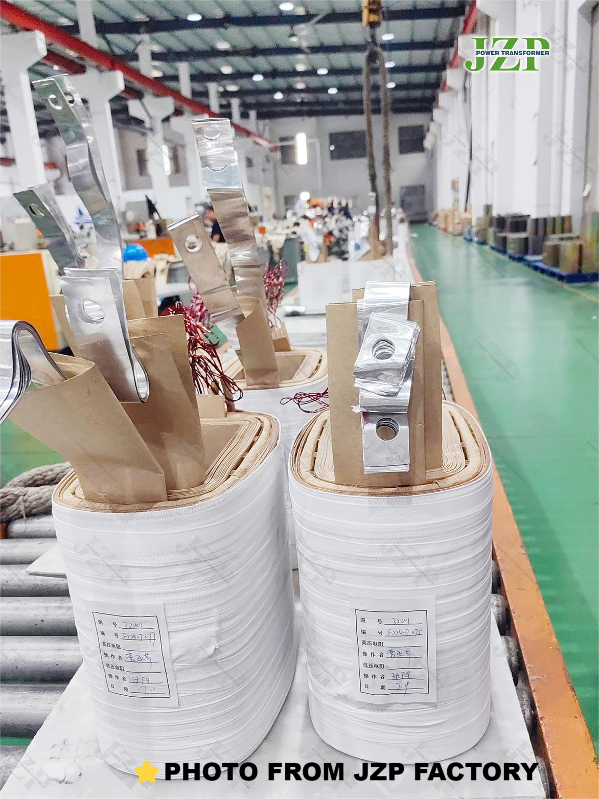
The transformer is made based on electromagnetic induction. It consists of an iron core made of silicon steel sheets (or silicon steel sheets) and two sets of coils wound on the iron core. The iron core and the coils are insulated from each other and have no electrical connection.
It has been theoretically confirmed that the voltage ratio between the primary coil and the secondary coil of the transformer is related to the ratio of the number of turns of the primary coil and the secondary coil, which can be expressed by the following formula: primary coil voltage/secondary coil voltage = primary coil turns/secondary coil turns. The more turns, the higher the voltage. Therefore, it can be seen that if the secondary coil is less than the primary coil, it is a step-down transformer. On the contrary, it is a step-up transformer.

2. What is the current relationship between the primary coil and the secondary coil of the transformer?
When the transformer is running with a load, the change in the secondary coil current will cause a corresponding change in the primary coil current. According to the principle of magnetic potential balance, it is inversely proportional to the current of the primary and secondary coils. The current on the side with more turns is smaller, and the current on the side with fewer turns is larger.
It can be expressed by the following formula: primary coil current/secondary coil current = secondary coil turns/primary coil turns.
3. How to ensure that the transformer has a rated voltage output?
Voltage that is too high or too low will affect the normal operation and service life of the transformer, so voltage regulation is necessary.
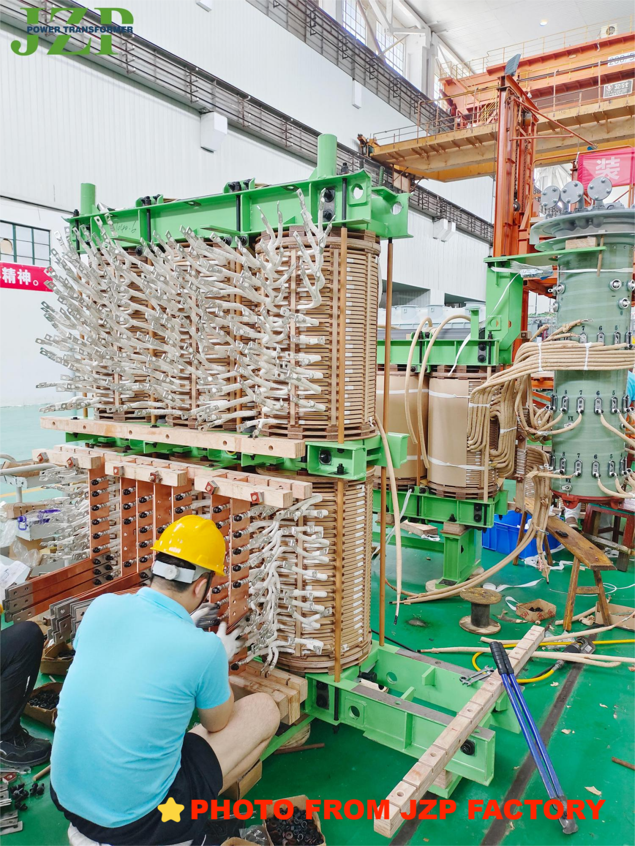
The method of voltage regulation is to lead out several taps in the primary coil and connect them to the tap changer. The tap changer changes the number of turns of the coil by rotating the contacts. As long as the position of the tap changer is turned, the required rated voltage value can be obtained. It should be noted that voltage regulation should usually be performed after the load connected to the transformer is cut off.

4. What are the losses of the transformer during operation? How to reduce the losses?
The losses in transformer operation include two parts:
(1) It is caused by the iron core. When the coil is energized, the magnetic lines of force are alternating, causing eddy current and hysteresis losses in the iron core. This loss is collectively called iron loss.
(2) It is caused by the resistance of the coil itself. When current passes through the primary and secondary coils of the transformer, power loss will be generated. This loss is called copper loss.
The sum of iron loss and copper loss is the transformer loss. These losses are related to the transformer capacity, voltage and equipment utilization. Therefore, when selecting a transformer, the equipment capacity should be consistent with the actual usage as much as possible to improve equipment utilization, and care should be taken not to operate the transformer under light load.
5. What is the nameplate of a transformer? What are the main technical data on the nameplate?
The nameplate of a transformer indicates the performance, technical specifications and application scenarios of the transformer to meet the user's selection requirements. The main technical data that should be paid attention to during selection are:
(1) The kilovolt-ampere of the rated capacity. That is, the output capacity of the transformer under rated conditions. For example, the rated capacity of a single-phase transformer = U line × I line; the capacity of a three-phase transformer = U line × I line.
(2) The rated voltage in volts. Indicate the terminal voltage of the primary coil and the terminal voltage of the secondary coil (when not connected to a load) respectively. Note that the terminal voltage of a three-phase transformer refers to the line voltage U line value.
(3) The rated current in amperes. Refers to the line current I line value that the primary coil and the secondary coil are allowed to pass through for a long time under the conditions of rated capacity and allowable temperature rise.
(4) Voltage ratio. Refers to the ratio of the rated voltage of the primary coil to the rated voltage of the secondary coil.
(5) Wiring method. A single-phase transformer has only one set of high and low voltage coils and is only used for single-phase use. A three-phase transformer has a Y/△ type. In addition to the above technical data, there are also the rated frequency, number of phases, temperature rise, impedance percentage of the transformer, etc.

6. What tests should be done on the transformer during operation?
In order to ensure the normal operation of the transformer, the following tests should be carried out frequently:
(1) Temperature test. The temperature is very important to determine whether the transformer is operating normally. The regulations stipulate that the upper oil temperature shall not exceed 85C (i.e., the temperature rise is 55C). Generally, transformers are equipped with special temperature measuring devices.
(2) Load measurement. In order to improve the utilization rate of the transformer and reduce the loss of electric energy, the power supply capacity that the transformer can actually bear must be measured during the operation of the transformer. The measurement work is usually carried out during the peak period of electricity consumption in each season, and is directly measured with a clamp ammeter. The current value should be 70-80% of the rated current of the transformer. If it exceeds this range, it means overload and should be adjusted immediately.
(3) Voltage measurement. The regulations require that the voltage variation range should be within ±5% of the rated voltage. If it exceeds this range, the tap should be used to adjust the voltage to the specified range. Generally, a voltmeter is used to measure the secondary coil terminal voltage and the terminal voltage of the end user respectively.
Conclusion: Your Reliable Power Partner Choose JZP for your power distribution needs and experience the difference that quality, innovation, and reliability can make. Our Single Phase Pad-Mounted Transformers are engineered to deliver superior performance, ensuring your power systems operate smoothly and efficiently. Contact us today to learn more about our products and how we can help you achieve your power distribution goals.
Post time: Jul-19-2024

