

Introduction
Transformer is a static device which transforms AC electrical power from one voltage to another voltage keeping the frequency same by electromagnetic induction principle.
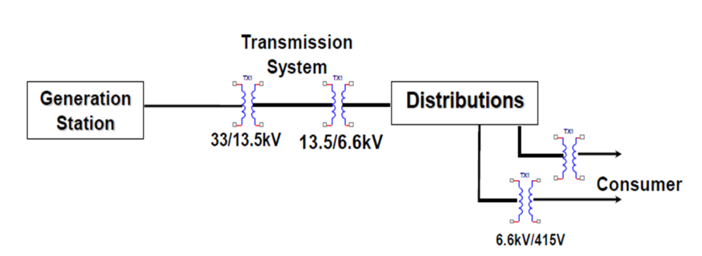
Input to a transformer and output from a transformer both are alternating quantities (AC).Electrical energy is generated and transmitted at an extremely high voltages. The voltage is to be then reduced to a lower value for its domestic and industrial use. When the transformer changes the voltage level, it changes the current level also.
Working Principle
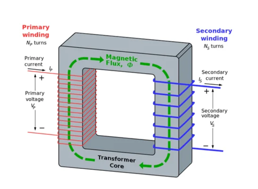
The primary winding is connected to the single – phase ac supply, an ac current starts flowing through it. The ac primary current produces an alternating flux (Ф) in the core. Most of this changing flux gets linked with the secondary winding through the core.
The varying flux will induce voltage into the secondary winding according to the faraday’s laws of electromagnetic induction. Voltage level change but frequency i.e. time period remains same. There is no electrical contact between the two winding, an electrical energy gets transferred from primary to the secondary.
A simple transformer consists of two electrical conductors called the primary winding and the secondary winding. Energy is coupled between the windings by the time varying magnetic flux that passes through( links) both primary and secondary windings.
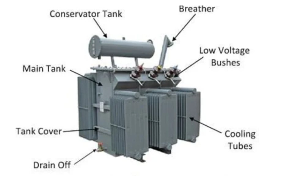
Essential Accessories of Power Transformer
1.Buchholz relay
This relay is designed to detect transformer internal fault in the initial stage to avoid major breakdown. The upper float rotates & switches contacts close & thus giving alarm.
2.Oil Surge Relay
This relay can be checked by pressing test switch provided on top side. Here only one contact is provided which gives trip signal on operation of float. By shorting contact externally by link, trip circuit can also be checked.
3.Explosion Vent
It consists of a bent pipe with Bakelite diaphragm at both ends. A protective wire mesh is fitted on the opening of transformer to prevent the pieces of ruptured diaphragm from entering the tank.
4.Pressure Relief Valve
When the pressure in the tank rises above pre- determined safe limit, this valve operates & performs the following functions: –
Allows the pressure to drop by instantaneously opening the port.
Gives visual indication of valve operation by raising a flag.
Operates a micro switch, which gives trip command to breaker.
5.Oil Temperature Indicator
It is dial type thermometer, works on the vapour pressure principle. It is also known as magnetic oil gauge (MOG). It has a pair of magnet. The metallic wall of conservator tank separates magnets without any through hole.Magnetic field comes out and it is used for indication.
6.Winding Temperature Indicator
It is also similar to OTI but has some changes. It consists of a probe fitted with 2 capillaries. Capillaries are connected with two separate bellows(operating/compensating). These bellows are connected with temperature indicator.
7.Conservator
As expansion and contraction occurs in transformer main tank, consequently the same phenomena takes place in conservator as it is connected to main tank through a pipe.
8.Breather
This is a special air filter incorporating a dehydrating material, called, Silica Gel. It is used to prevent the ingress of moisture and contaminated air into conservator.
9.Radiators
Small Transformers are provided with welded cooling tubes or pressed sheet steel radiators. But large transformers are provided with detachable radiators plus valves. For additional cooling, exhaust fans are provided on radiators.
10.Tap Changer
As load on the transformer increases, secondary terminal voltage decreases.There are two type of tap changer.
A.Off Load Tap Changer
In this type, before moving the selector, transformer is made OFF from both ends. Such tap changers have fixed brass contacts, where taps are terminated. The moving contacts are made of brass in the shape of either roller or segment.
B.On Load Tap Changer
In short we call it as OLTC. In this, taps can be changed manually by mechanical or electrical operation without making off the transformer. For mechanical operation, interlocks are provided for non-operation of O.L.T.C. below lowest tap position and above highest tap position.
11.RTCC (Remote tap change control cubicle)
It is used for tap changing by manually or automatically through Automatic Voltage Relay (AVR) which is set +/- 5% of 110 Volt (Reference taken from secondary side PT voltage).
Post time: Sep-02-2024