A power transformer with an on-load tap changer (OLTC) can regulate voltage while the transformer is still in use, without interrupting the power supply. OLTCs are important components in power systems because they maintain the desired voltage output. JIEZOU POWER manufactures the power transformers, we will prefer to choose MR or ABB brand.
Performance of on-load tap changer:
The operation principle of a tap changer installed in a transformer can best be explained with an example:
A car equipped with automatic transmission and cruise control drives along a hilly route. The cruise control ensures, that the speed once set is maintained. Accordingly, the automatic transmission shifts up or down depending on the gradient.
The tap changer in the transformer (car) works similar. If the values specified by a voltage regulation (cruise control) are exceeded or undershot in times of high or low electricity consumption (hilly route) - the switch changes (automatic transmission) in fractions of a second from one transformer winding to the next suitable level and thus ensures that the voltage remains constant.
On-load tap changer applications:
1.Basic arrangements of regulating winidng.
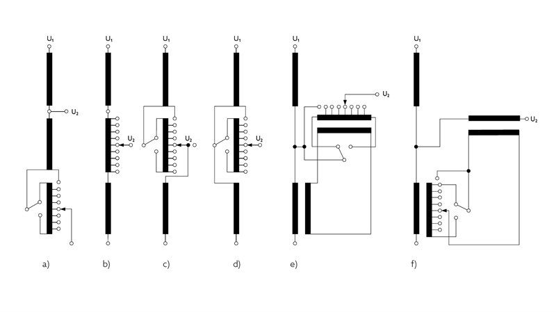
The following basic arrangements of tap windings are used (fig. 5): Linear arrangement (fig. 5 a), is generally used on power transformers with moderate regulating ranges up to a maximum of 20 %. The tapped turns are added in series with the main winding and changes the transformer ratio. The rated position can be any one of the tap positions.
With a reversing change-over selector (fig. 5 b) the tap winding is added to or subtracted from the main winding so that the regulating range can be doubled or the number of taps reduced. During this operation, the tap winding is disconnected from the main winding (for problems arising from this disconnection see chapter 6.2). The greatest copper losses occur, however, in the position with the min i mum number of effective turns. This reversing operation is realized using a change-over selector which is part of the tap selector or of the selector switch (arcing tap switch). The rated position is normally the mid position or neutral position.
The double reversing change-over selector (fig. 5 c) avoids the disconnection of tap winding during the change-over operation. In phase-shifting transformers (PST) this apparatus is called the advance-retard switch (ARS).
Using a coarse change-over selector (fig. 5 d) the tap winding is connected either to the plus or minus tapping of the coarse winding. During coarse selector operation, the tap winding is disconnected from the main winding (special winding arrangements can cause the same disconnection problems as described above; in addition the series impedance of coarse winding/tap winding must be checked – see chapter 6.3). In this case, the copper losses are lowest in the position of the lowest effective number of turns. This advantage, however, places higher demands on insulation material and requires a larger number of windings.
The multiple coarse change-over selector (fig. 5 e) enables multiplication of the regulating range. It is mainly used for industrial process transformers (rectifier/furnace transformers). The coarse change-over selector is also part of the OLTC.
Which of these basic winding arrangements is used in each individual case depends on the system and operating requirements. These arrangements are applicable to two winding transformers as well as to autotransformers and to phase-shifting transformers (PST). Where the tap winding and therefore the OLTC is inserted in the windings (high-voltage or low-voltage side) depends on the transformer design and customer specifications.

( Figure 5 )
2.Examples of commonly used winding schemes
Two winding transformers with wye-connected windings have regulation applied to the neutral end, as shown in figure 6. This results in relatively simple and compact solutions for OLTCs and tap windings.
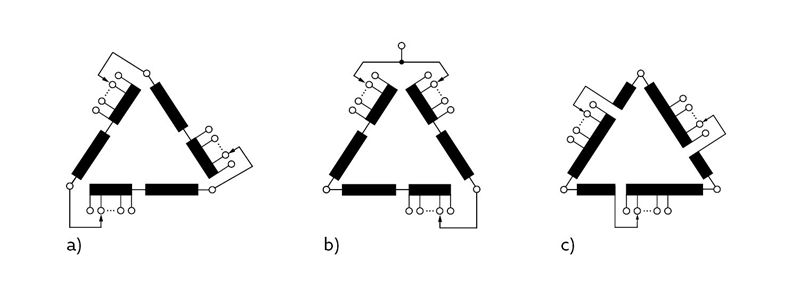
Regulation of delta-connected windings (fig. 7) requires a three-phase OLTC whose three phases are insulated according to the highest system voltage applied (fig. 7 a), or 3 single-phase OLTCs, or 1 single-phase and 1 two-phase OLTC (fig. 7 b). Today, the design limit for three-phase OLTCs with phase-to-phase insulation is the highest voltage for equipment of 145 kV (BIL 650 kV). To reduce the phase-to-phase stresses on the delta-OLTC the three pole mid-winding arrangement (fig. 7 c) can be used.

( Figure 6 )

( Figure 7)
For regulated autotransformers, fig. 8 shows various circuits. The most appropriate scheme is chosen with regard to regulating range, system conditions and/or requirements, as well as weight and size restrictions during transportation. Autotransformers are always wye-connected.
Neutral end regulation (fig. 8 a) may be applied with a ratio above 1:2 and a moderate regulating range up to 15 %. This operates with variable flux.
A scheme shown in fig. 8 c is used for regulating high voltage U1.
For low voltage U2 regulation, the circuits fig. 8 b, 8 d, 8 e and 8 f are applicable. The arrangements fig. 8 e and 8 f are two core solutions. Circuit fig. 8 f operates with variable flux in the series transformer, but it has the advantage that a neutral end OLTC can be used. In the case of arrangement according to fig. 8 e, the main and regulating transformers are often placed in separate tanks to reduce transport weight. At the same time, this solution allows some degree of phase shifting by changing the excitation connections within the intermediate circuit.

( Figure 8 )
3.Phase-shifting transformers
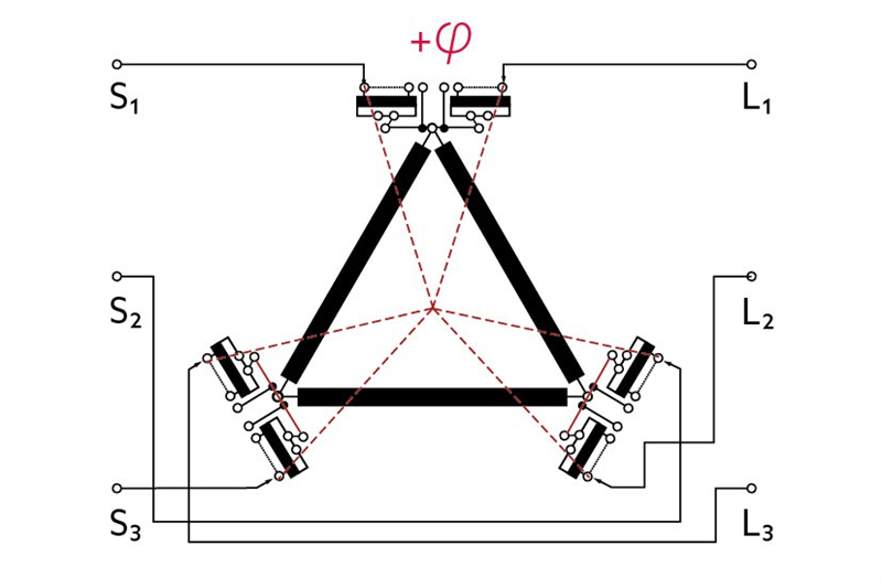
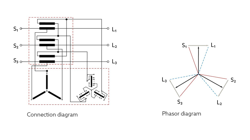
Over the last few years, the importance of phase-shifting transformers used to control the power flow on transmission lines in meshed networks has been steadily increasing . The fact that IEEE provides a “Guide for the Application, Specification and Testing of Phase-Shifting Transformers“ proves the demand for PSTs. These transformers often require regulating ranges which exceed those normally used. To achieve such regulating ranges, special circuit arrangements are necessary. Two examples are given in fig. 9 and fig. 10.
Fig. 9 shows a circuit with direct line-end regulation, fig. 10 an intermediate circuit arrangement. Fig. 9 illustrates very clearly how the phase-angle between the voltages of the source and load systems can be varied by the OLTC position. Various other circuit arrangements have been implemented.
The number of OLTC operations of PSTs is much higher than that of other regulating transformers in networks (10 to 15 times higher). In some cases, according to regulating ranges – especially for line-end arrangements (fig. 9) – the transient overvoltage stresses over tapping ranges have to be limited by applying non-linear resistors. In addition, the short-circuit current ability of the OLTC must be checked, as the short-circuit power of the network determines the current. The remaining features of OLTCs for such transformers can be selected according to the usual rules.

( Figure 9 )

(Figure 10)
Significant benefits resulting from the use of a PST are:
-Reduction of overall system losses by eliminating circulating currents
-Improvement of circuit capability by proper load management
-Improvement of circuit power factor
Control of power flow to meet contractual requirements
Post time: Dec-03-2024

